Product Overview
Reliable custom rubber parts for industrial applications
Quick Answer
A flanged rubber pneumatic diaphragm combines a flexible pressure-responsive membrane with an integrated perimeter flange for clamping and sealing. Diameter, thickness, flange geometry, rubber compound, Shore A hardness, membrane profile, mounting features, and tolerances can be customized for pneumatic valves, actuators, regulators, cylinders, and control devices.
A flanged rubber pneumatic diaphragm combines a flexible pressure-responsive membrane with an integrated flange for clamping and sealing inside pneumatic valves, actuators, regulators, and control devices. Diameter, thickness, flange geometry, rubber material, Shore A hardness, and mounting features can be customized. Final specifications depend on air pressure, temperature, stroke, cycling frequency, contact media, and housing design.
Flanged Rubber Pneumatic Diaphragm — Precision Molded for Leak-Tight Pneumatic Actuation
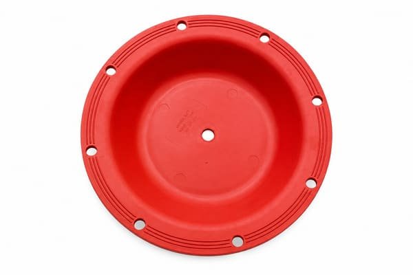
A flanged rubber pneumatic diaphragm is a flexible molded membrane with an integral outer flange, typically featuring a ring of bolt holes, that clamps directly between the two halves of a pneumatic actuator or valve housing to seal the control chamber while its center flexes in response to air pressure changes. The flanged edge distributes clamping force evenly around the diaphragm’s perimeter, eliminating the need for a separate gasket at the mounting interface and ensuring the pneumatic chamber remains airtight throughout repeated actuation cycles. This design is standard across pilot-operated valves, pneumatic actuators, and pressure control equipment where a bolted, replaceable diaphragm interface is preferred over a bonded or press-fit installation.
Key Specifications
| Parameter | Typical Range/Option |
|---|---|
| Available Materials | EPDM, NBR (Nitrile), Viton (FKM), Silicone |
| Flange Type | Bolt-hole ring flange for clamped installation between actuator/valve body halves |
| Reinforcement | Fabric-reinforced (nylon or polyester) or unreinforced |
| Diaphragm Shapes | Flat, convoluted (rolling), dished profiles |
| Hardness Range | Typically 50–75 Shore A, depending on application |
| Diameter Range | Custom, sized to match specific pneumatic actuator or valve model |
| Attachment Feature | Center hole, bonded metal stud, or plain center for stem/disc linkage |
| Manufacturing Process | Compression molding, transfer molding |
| Common Applications | Pilot-operated valves, pneumatic actuators, pressure/level control valves |
What Is a Flanged Rubber Pneumatic Diaphragm?
A pneumatic diaphragm sits inside an actuator or valve’s control chamber, flexing in response to air pressure delivered by a pilot valve, solenoid, or positioner, with this flexing motion driving an attached stem or disc to open, close, or throttle a main flow path. The flanged edge of the diaphragm is where it seats against the actuator housing, and when bolted together, the bolt-hole ring compresses the diaphragm material evenly around its circumference to form an airtight seal without relying on a separate gasket. Because the flange itself performs a sealing function in addition to structural mounting, its dimensional accuracy—including bolt-hole spacing, flange thickness, and outer diameter—is just as critical to reliable pneumatic performance as the flexing center section.
Available Materials and Their Properties
| Material | Key Properties | Typical Applications |
|---|---|---|
| EPDM | Excellent weather, ozone, and steam resistance; stable in potable water | Water distribution valves, irrigation systems, outdoor pneumatic actuators |
| NBR (Nitrile) | Strong oil and fuel resistance | Hydraulic and fuel-handling pneumatic valves |
| Viton (FKM) | Superior chemical and high-temperature resistance | Chemical process pneumatic valves, aggressive fluid handling |
| Silicone | Wide temperature range, good flexibility | Specialty pneumatic valves requiring temperature extremes |
EPDM is the most common compound for pneumatic valves in water and outdoor applications because it combines long-term ozone and UV resistance with chemical stability in potable water systems.
Why the Flanged Design Matters for Pneumatic Diaphragms
- Even clamping force distribution — the bolt-hole ring spreads clamping pressure evenly around the diaphragm’s circumference, reducing the risk of localized air leak paths compared to non-flanged designs.
- Gasket-free airtight sealing — the diaphragm itself acts as the seal at the flange interface, eliminating the need for a separate gasket and reducing potential leak points in the pneumatic chamber.
- Simplified maintenance — because the diaphragm bolts directly between two flanged halves, replacement during maintenance is straightforward without specialized bonding or vulcanizing equipment.
- Consistent actuation force — a properly sealed flange prevents air pressure loss around the diaphragm edge, ensuring the actuator delivers full, consistent force to the valve stem.
- Compatibility with standard actuator housings — flanged diaphragms are typically manufactured to match recognized bolt-circle patterns for common pneumatic actuator and valve body designs.
Why Fabric Reinforcement Matters
- High-cycle fatigue resistance — pneumatic diaphragms often cycle frequently or hold a modulating position continuously, and fabric reinforcement resists elongation and cracking that would otherwise occur much faster in an unreinforced diaphragm.
- Consistent actuation force — a reinforced diaphragm maintains predictable stiffness and flex behavior over its service life, ensuring the pneumatic actuator delivers consistent force to the valve stem.
- Dimensional stability under pressure — the fabric layer prevents the diaphragm from ballooning or distorting under air pressure, helping maintain accurate valve positioning.
- Extended service life — reinforcement significantly reduces the risk of diaphragm rupture, the most common failure mode requiring valve disassembly and downtime.
Diaphragm Shape and Attachment Options
- Convoluted (rolling) diaphragms — feature a folded profile that rolls during flexing, allowing longer stroke length for modulating pneumatic valves.
- Flat diaphragms — used in simpler on/off pneumatic valves with shorter stroke requirements.
- Center-hole designs — molded with a center opening that fits over the valve’s internal stem for direct disc linkage.
- Bonded metal stud designs — a metal insert molded directly into the diaphragm center bolts securely to the valve’s disc assembly, reducing the risk of detachment under repeated cycling.
Manufacturing Process
Flanged rubber pneumatic diaphragms are produced using compression molding or transfer molding, where the rubber compound is cured under heat and pressure within a mold cavity that forms both the flexing center section and the flanged bolt-hole edge in a single molding operation. Bolt holes are typically molded directly into the flange during curing, ensuring consistent hole placement and bolt-circle diameter without requiring secondary drilling operations. When fabric reinforcement is specified, pre-cut layers are positioned within the mold cavity alongside the rubber compound before curing, with strict process control over cure temperature, time, and mold pressure ensuring complete fabric-to-rubber bonding without air entrapment.
Common Applications
- Pilot-operated pneumatic control valves in water distribution and municipal piping systems.
- Pneumatic actuators for industrial process control valves.
- Pressure-reducing, pressure-sustaining, and level control valves using pneumatic diaphragm actuation.
- Industrial process valves handling water, oil, or chemical media requiring diaphragm-based pneumatic control.
- HVAC and building automation pneumatic control valves.
Custom Manufacturing Options
- Custom flange diameter, bolt-hole count, and bolt-circle pattern to match specific actuator or valve body designs.
- Custom diaphragm profile — flat, dome, dished, or convoluted — matched to stroke and pressure requirements.
- Custom fabric reinforcement type and ply count matched to expected cycling frequency and pressure differential.
- Custom rubber compound selection based on the process fluid, temperature range, and compliance requirements.
- Custom bonded metal stud or center-hole configuration for direct stem/disc attachment.
- Reverse-engineering service to reproduce diaphragms from a sample part or valve/actuator model number.
- Prototype and low-volume sampling available prior to full production tooling commitment.
FAQ
Can the flange dimensions be customized?
Yes. Flange diameter, width, thickness, sealing bead, bolt pattern, and transition to the flexible membrane can be customized. The housing groove, mating surfaces, clamping force, critical tolerances, and available movement space should be provided before tooling development.
How should the rubber material be selected?
Material selection depends on compressed-air quality, lubricants, moisture, process media, temperature, pressure, cycling frequency, and environmental exposure. Complete application conditions should be reviewed before the compound and Shore A hardness are confirmed. Compatibility testing may be required.
Can fabric reinforcement be incorporated?
Fabric reinforcement can be evaluated when required by the pressure, dimensions, stroke, and movement pattern. The fabric type, weave, orientation, layer arrangement, and position must support the required flexibility. Reinforcement availability and construction are confirmed during technical review.
Can a physical sample be used for development?
Yes. A physical sample can support structural and dimensional evaluation. Application conditions and available material information should also be provided. Wear, swelling, hardening, tearing, or permanent deformation may affect the measured dimensions of a used diaphragm.
Are prototype samples available?
Sample availability depends on the diaphragm geometry, rubber compound, tooling requirements, and requested quantity. Initial samples can be arranged after technical review. Dimensions, flange fit, sealing, movement, hardness, and functional acceptance criteria should be defined before approval.
How are tooling, MOQ, and lead time confirmed?
Tooling, MOQ, and lead time depend on the diaphragm dimensions, flange design, compound, reinforcement, inspection requirements, sample approval process, and order quantity. These details are confirmed after reviewing the complete specification and estimated annual demand.
Request a Custom Quote
Send your 2D drawing, 3D model, or physical sample for a flanged rubber pneumatic diaphragm quotation. Include dimensions, flange geometry, contact media, temperature, pressure, stroke, cycling frequency, material requirements, quantity, and estimated annual volume. Tooling, samples, MOQ, lead time, testing, and documentation will be confirmed after technical review.