Product Overview
Reliable custom rubber parts for industrial applications
Quick Answer
This cylinder head flange seal is a precision-molded gasket for cam covers, valve covers, coolant outlets and auxiliary engine-port interfaces. HNBR, FKM, ACM, VMQ and application-specific materials are available. Cross-section, passage geometry, locating features, bolt-hole pattern, Shore A hardness, tolerances and packaging can be customized according to the drawing.
This cylinder head flange seal is a precision-molded rubber gasket for cam covers, coolant outlets and auxiliary port flanges connected to the cylinder head. It helps control leakage of engine oil, oil mist, blow-by gas or coolant at compatible external interfaces. HNBR, FKM, ACM, VMQ and application-specific compound options are available according to temperature and media exposure.
Product Overview
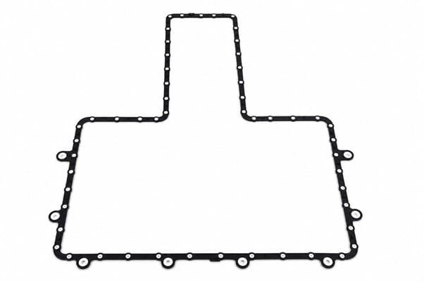
The cylinder head flange seal is an elastomeric gasket installed between a cylinder-head port or cover surface and a mating engine component. Common positions include cam covers, valve covers, coolant outlet housings, breather-port covers and auxiliary flange connections. Unlike the main cylinder head gasket between the engine block and cylinder head, this product is designed for external flange interfaces with lower pressure but demanding thermal and chemical exposure. The molded profile maintains controlled sealing contact under bolt compression, vibration and repeated thermal cycling. Depending on the assembly design, the seal can include a groove-matched frame, D-ring profile, multi-lip cross-section, locating tabs or retention pegs.
Key Features
- Designed for cam covers, coolant outlets, breather ports and compatible auxiliary cylinder-head flange interfaces.
- Helps reduce external leakage of engine oil, oil mist, blow-by gas or coolant according to the installation position.
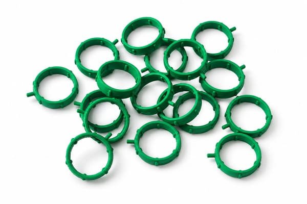
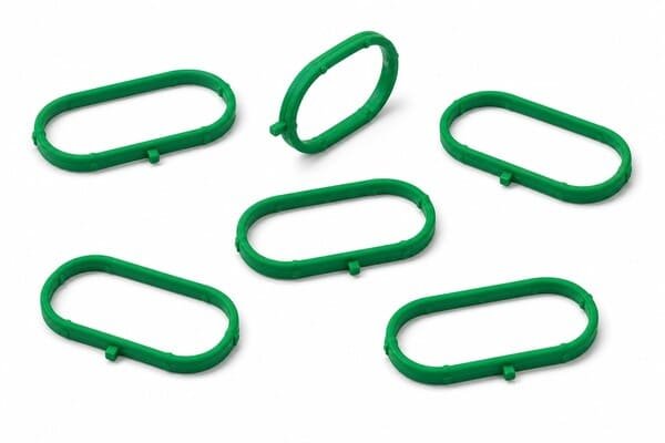
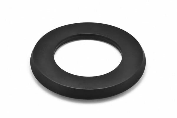
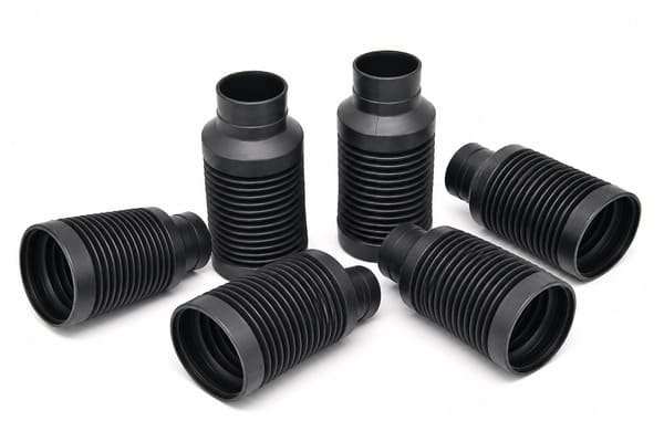
- Available as molded frames, D-rings, square-cut seals, multi-lip profiles and ribbed O-ring-style gaskets.
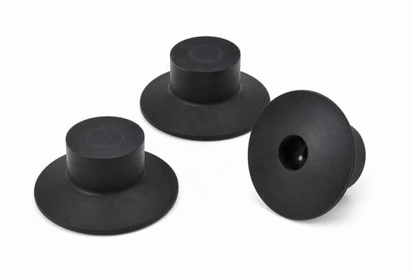
- Optional locating tabs and retention pegs help maintain gasket position during manual or automated assembly.
- Profile geometry can accommodate controlled flange movement during engine thermal cycling.
- Critical sealing surfaces can be manufactured with defined flash-control requirements.
- HNBR, FKM, ACM, VMQ and application-specific compounds are available according to the working environment.
- Custom dimensions, Shore A hardness, tolerances, packaging and inspection requirements are available upon request.
Product Specifications
| Specification | Details |
|---|---|
| Product Name | Cylinder Head Flange Seal |
| Also Known As | Cam cover flange seal, valve cover gasket, cylinder-head auxiliary port seal or flange O-ring seal |
| Material | HNBR, FKM, ACM, VMQ or application-specific rubber compound. Material selection depends on the operating conditions. |
| Hardness | Available according to compound and sealing-profile requirements |
| Color | Black, green or application-specific color, depending on the selected compound |
| Manufacturing Process | Compression molding or injection molding, depending on the gasket structure |
| Profile Options | Molded frame, D-ring, square-cut seal, multi-lip gasket, ribbed O-ring-style profile or custom molded shape |
| Assembly Features | Optional locating tabs, retention pegs, alignment features and groove-fit structures |
| Application | Compatible external cylinder-head flange interfaces in automotive and industrial engine assemblies |
| Customization | Overall dimensions, thickness, cross-section, passage geometry, bolt-hole pattern, grooves, locating tabs, sealing lips, rubber compound, Shore A hardness, dimensional tolerance, flash-control requirements, packaging and inspection requirements can be reviewed according to the drawing. |
| MOQ | Contact us for details |
| Tooling | Tooling cost depends on the drawing and product structure |
| Sample Availability | Available upon request |
| Lead Time | Available upon request |
| Compliance Options | ASTM D2000, SAE J200, RoHS and REACH requirements can be reviewed according to the selected compound. Documentation is available upon request. |
Reference Variant: LJM20B-1008116
| Specification | Reference Details |
|---|---|
| Reference Part Number | LJM20B-1008116 |
| Reference Application | Cylinder-head cam-cover or auxiliary-port flange sealing |
| Material | HNBR |
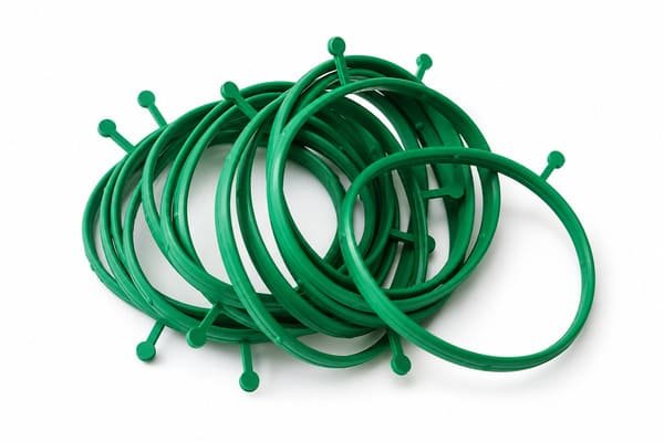
| Color | Green series color code |
| Hardness | 60–75 Shore A |
| Temperature Range | -40°C to +150°C |
| Media Resistance | Engine oil, oil mist, blow-by gas and coolant exposure according to the installation position |
| Installation | Groove-matched dry-fit installation. Sealant is not required unless specified by the assembly drawing. |
| Standard Packaging | 500 pcs per bag |
| Compatibility Review | LJM20B engine-series applications and equivalent interfaces can be reviewed according to the engine code, flange drawing and physical sample. |
Common Cylinder Head Flange Seal Interfaces
| Installation Position | Primary Sealing Function | Key Selection Factors |
|---|---|---|
| Cam Cover / Valve Cover Flange | Helps control engine-oil mist and blow-by gas leakage around the upper engine cover | Perimeter groove, cover flatness, oil exposure, temperature and bolt spacing |
| Coolant Outlet Housing | Helps control coolant leakage at the cylinder-head water-jacket outlet | Coolant formulation, port geometry, pressure, temperature and flange compression |
| Breather or Oil-Filler Port Flange | Helps seal crankcase ventilation or service-port interfaces | Oil mist, blow-by gas, groove structure and locating features |
| Sensor or Auxiliary Housing Flange | Provides application-specific sealing around an external cylinder-head connection | Passage geometry, contact media, bolt pattern and dimensional tolerance |
Profile Selection Guide
| Profile Type | Typical Characteristics | Recommended Use |
|---|---|---|
| Molded Frame Gasket | Application-specific perimeter profile with optional ribs and locating pegs | Cam-cover and valve-cover grooves with complex outlines |
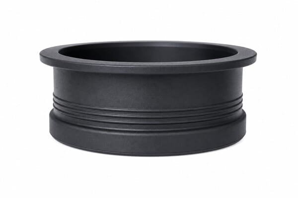
| D-Ring Profile | Flat contact surface with controlled compression behavior | Grooved flange interfaces requiring stable face sealing and defined orientation |
| Square-Cut Seal | Broad contact surface and simple cross-section | Flat flange interfaces and application-specific retaining grooves |
| Multi-Lip Profile | Multiple localized sealing lines across the flange interface | Applications requiring controlled sealing contact under limited flange compression |
| Ribbed O-Ring-Style Profile | Raised ribs provide localized contact pressure and groove retention | Auxiliary-port and coolant-outlet interfaces with defined housing grooves |
Material Selection Guide
| Rubber Material | Typical Shore A Hardness | Typical Temperature Range | Key Characteristics | Recommended Applications |
|---|---|---|---|---|
| HNBR | 60–75 Shore A | -40°C to +150°C | Mechanical strength, low compression set and resistance to engine oil, oil mist and blow-by gas | Cam covers, valve covers and auxiliary cylinder-head flange interfaces |
| FKM | 70–80 Shore A | -20°C to +200°C | Heat resistance and compatibility with demanding oil, fuel-vapor and chemical exposure | Turbocharged engines, higher-temperature interfaces and severe-duty applications |
| ACM | 65–75 Shore A | -30°C to +150°C | Resistance to hot engine oils and practical cost-to-performance balance | High-volume cam-cover and valve-cover applications involving lubricant exposure |
| VMQ Silicone | 55–65 Shore A | -50°C to +180°C | Low-temperature flexibility and elastic behavior across a broad temperature range | Cold-climate platforms and flange interfaces requiring a flexible molded profile |
| EPDM | Available upon request | Available according to compound | Compatibility with coolant, water, ozone and weather exposure | Coolant-only flange interfaces without hydrocarbon-oil contact |
Applications
Cylinder head flange seals can be used throughout the upper engine assembly where a cover, housing or auxiliary component connects to a cylinder-head port. Typical applications include cam covers, valve covers, coolant outlet housings, breather-port flanges and sensor-related interfaces. The gasket maintains sealing contact while the mating components expand, contract and vibrate during engine operation. The correct profile depends on the passage geometry, groove dimensions, bolt spacing and flange flatness. Material selection should be based on the actual contact media, including engine oil, oil mist, blow-by gas or coolant. Direct combustion-chamber sealing requires a different gasket structure.
Customization Options
Custom cylinder head flange seals can be developed according to 2D drawings, 3D STEP models, OEM part numbers or physical samples. Buyers can specify the flange outline, passage geometry, thickness, cross-section, groove fit, sealing lips, locating tabs, retention pegs, bolt-hole pattern, material, Shore A hardness and dimensional tolerance. Flash-control requirements should be identified for critical sealing surfaces. Please provide the engine model, installation position, operating temperature, contact media, flange-compression requirement, prototype quantity, estimated annual volume and packaging method. Tooling cost depends on the drawing and product structure.
Quality Documentation Options
- Material test reports are available upon request.
- Dimensional inspection reports can be prepared according to the agreed drawing.
- PPAP Level 3 documentation can be reviewed for applicable automotive projects.
- RoHS and REACH documentation is available upon request for applicable compounds.
- Heat-aging and compression-set test requirements can be reviewed according to the project specification.
- Batch packaging, part marking and private-label requirements can be evaluated for OEM and distributor orders.
What Information Should Buyers Provide for a Quote?
- 2D drawing, 3D model, OEM part number or physical sample
- Engine model and cylinder-head flange location
- Mating-component drawing
- Overall gasket dimensions and tolerances
- Passage geometry
- Thickness and cross-section
- Bolt-hole diameter and hole pattern, if applicable
- Groove width and groove depth
- Locating-tab or retention-peg requirements
- Rubber material
- Shore A hardness
- Continuous and peak operating temperature
- Contact media, including engine oil, blow-by gas or coolant
- Flange-compression requirements
- Required quantity
- Estimated annual volume
- Compliance requirements
- Packaging requirements
FAQ
What is a cylinder head flange seal used for?
A cylinder head flange seal is installed between an external cylinder-head port or cover surface and a connected engine component. It helps control leakage of engine oil, oil mist, blow-by gas or coolant according to the installation position.
Is a cylinder head flange seal the same as the main cylinder head gasket?
No. The main cylinder head gasket seals the joint between the engine block and cylinder head under combustion pressure. A cylinder head flange seal is used at an external interface such as a cam cover, coolant outlet, breather port or auxiliary housing connection.
How should buyers select HNBR, FKM, ACM or VMQ?
HNBR can be reviewed for oil, oil-mist and blow-by exposure at standard cylinder-head temperatures. FKM is suitable for more demanding heat and chemical conditions. ACM can be evaluated for hot-engine-oil exposure in high-volume applications. VMQ can be considered where broad temperature flexibility is required.
Is sealant required during installation?
Groove-matched molded seals are commonly installed dry without liquid sealant. The gasket should be seated evenly in the groove before the flange bolts are tightened. The correct installation method must follow the engine drawing or service specification for the specific interface.
Can you supply the LJM20B-1008116 reference variant?
The LJM20B-1008116 HNBR reference variant can be reviewed for suitable cylinder-head auxiliary-port or cover-flange applications. Please provide the engine code, mating-flange drawing, required quantity and packaging requirements so the dimensional interface and supply details can be confirmed.
Can complete cam-cover gasket kits be supplied?
Complete gasket-kit requirements can be reviewed according to the engine model and kit contents. A kit may include the main cam-cover gasket, spark-plug-well seals, bolt grommets and auxiliary flange seals. Please submit the engine code and required component list for evaluation.
Request a Custom Quote
Send your cylinder-head flange drawing, mating-component drawing, 3D STEP model, OEM part number or physical sample for technical review. Please include the installation position, groove dimensions, gasket profile, contact media, operating temperature, compound preference, prototype quantity, estimated annual demand and packaging requirements.